Custom LiDAR 사용 방법
본 페이지는 현재 시뮬레이터에서 제공하는 LiDAR Sensor 외의 사용자가 정의한 LiDAR를 사용하는 방법을 소개한다.
1. Custom LiDAR Template 파일을 “Lidar.json“ 으로 저장
아래의 Custom LiDAR Template 은 Custom LiDAR의 이름, Field of View, Rotation Frequency 등을 포함한다. Template 파일을 JSON 파일 형식으로 아래 디렉토리에 저장하면 MORAI SIM: Drive 시뮬레이터에서 Template 대로 Custom LiDAR 를 사용할 수 있다.
Template json 파일 디렉토리 : SaveFile/LidarTemplate/Lidar.json
Template json 파일 예시 :
CODE{ "Name": "Custom", "LaserCount": 128, "MinDistance": 0.5, "MaxDistance": 245.0, "RotationFrequency": 10.0, "MeasurementsPerRotation": 1800, "FieldOfView": 40.0, "VerticalRayAngles": [ -11.742, -1.99, 3.4, -5.29, -0.78, 4.61, -4.08, 1.31, -6.5, -1.11, 4.28, -4.41, 0.1, 6.48, -3.2, 2.19, -3.86, 1.53, -9.244, -1.77, 2.74, -5.95, -0.56, 4.83, -2.98, 2.41, -6.28, -0.89, 3.62, -5.07, 0.32, 7.58, -0.34, 5.18, -3.64, 1.75, -25, -2.43, 2.96, -5.73, 0.54, 9.7, -2.76, 2.63, -7.65, -1.55, 3.84, -4.85, 3.18, -5.51, -0.12, 5.73, -4.3, 1.09, -16.042, -2.21, 4.06, -4.63, 0.76, 15, -3.42, 1.97, -6.85, -1.33, -5.62, -0.23, 5.43, -3.53, 0.98, -19.582, -2.32, 3.07, -4.74, 0.65, 11.75, -2.65, 1.86, -7.15, -1.44, 3.95, -2.1, 3.29, -5.4, -0.01, 4.5, -4.19, 1.2, -13.565, -1.22, 4.17, -4.52, 0.87, 6.08, -3.31, 2.08, -6.65, 1.42, -10.346, -1.88, 3.51, -6.06, -0.67, 4.72, -3.97, 2.3, -6.39, -1, 4.39, -5.18, 0.21, 6.98, -3.09, 4.98, -3.75, 1.64, -8.352, -2.54, 2.85, -5.84, -0.45, 8.43, -2.87, 2.52, -6.17, -1.66, 3.73, -4.96, 0.43 ], "rotCorrections": [ 6.354, 4.548, 2.732, 0.911, -0.911, -2.732, -4.548, -6.354, 6.354, 4.548, 2.732, 0.911, -0.911, -2.732, -4.548, -6.354, 6.354, 4.548, 2.732, 0.911, -0.911, -2.732, -4.548, -6.354, 6.354, 4.548, 2.732, 0.911, -0.911, -2.732, -4.548, -6.354, 6.354, 4.548, 2.732, 0.911, -0.911, -2.732, -4.548, -6.354, 6.354, 4.548, 2.732, 0.911, -0.911, -2.732, -4.548, -6.354, 6.354, 4.548, 2.732, 0.911, -0.911, -2.732, -4.548, -6.354, 6.354, 4.548, 2.732, 0.911, -0.911, -2.732, -4.548, -6.354, 6.354, 4.548, 2.732, 0.911, -0.911, -2.732, -4.548, -6.354, 6.354, 4.548, 2.732, 0.911, -0.911, -2.732, -4.548, -6.354, 6.354, 4.548, 2.732, 0.911, -0.911, -2.732, -4.548, -6.354, 6.354, 4.548, 2.732, 0.911, -0.911, -2.732, -4.548, -6.354, 6.354, 4.548, 2.732, 0.911, -0.911, -2.732, -4.548, -6.354, 6.354, 4.548, 2.732, 0.911, -0.911, -2.732, -4.548, -6.354, 6.354, 4.548, 2.732, 0.911, -0.911, -2.732, -4.548, -6.354, 6.354, 4.548, 2.732, 0.911, -0.911, -2.732, -4.548, -6.354 ], "CenterAngle": 0.0, "TextureHeightFactor": 32, "TextureWeightFactor": 2 }
현재 Custom LiDAR는 ROS 에서만 사용 가능하며, Lidar.json 파일 명으로 저장된 템플릿만 사용이 가능하다.
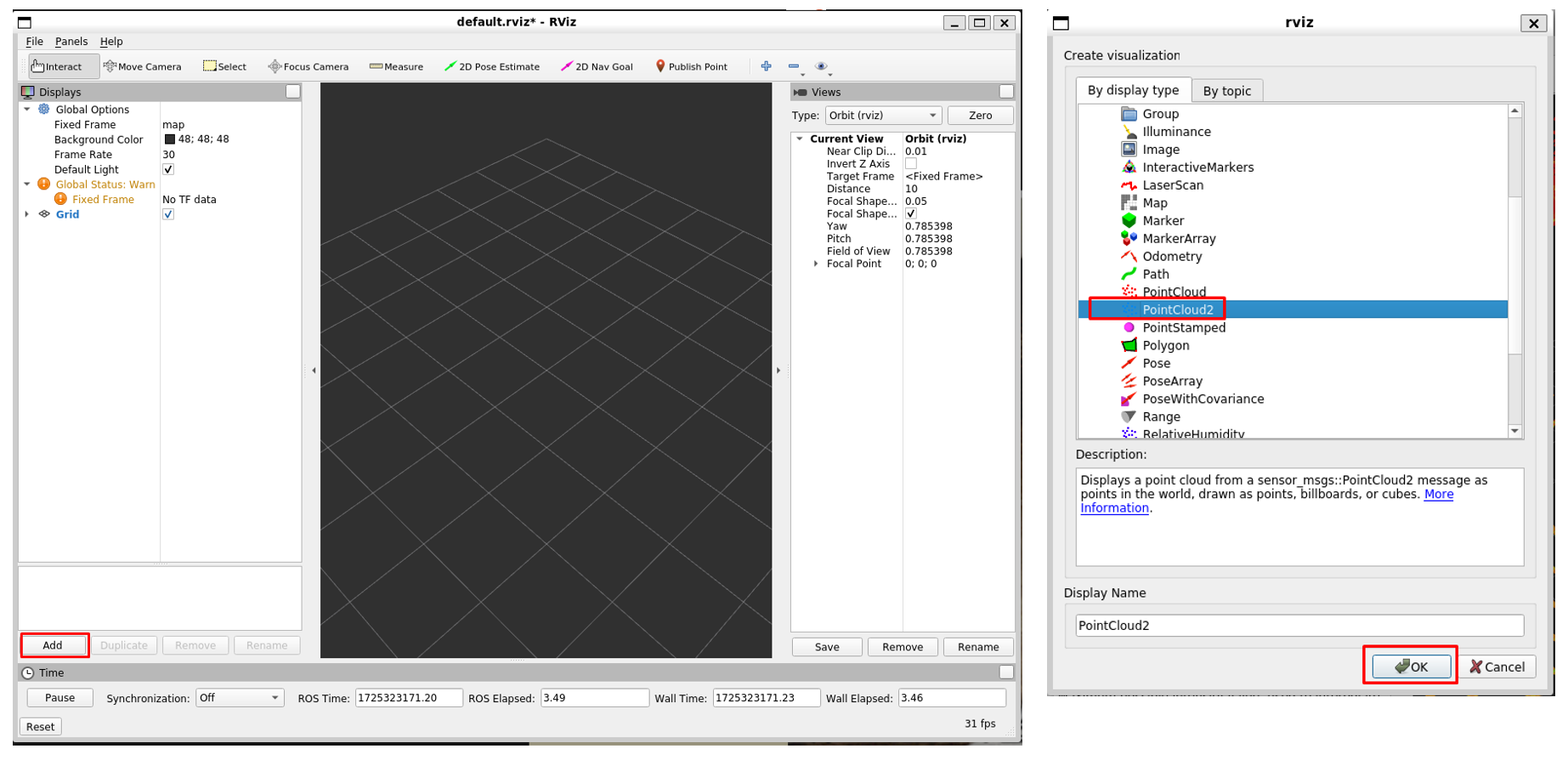
2. Rviz Setting
Rviz 를 실행하고 Add 를 클릭해 PointCloud2 Visualization 을 생성한다.
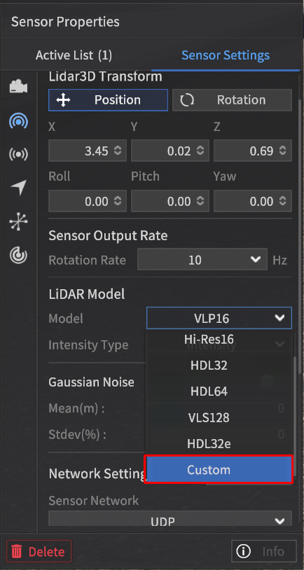
3. Custom LiDAR 세팅
기존에 센서를 생성하는 방법과 동일하게 Sensor 탭에서 3D LiDAR 를 생성 후 아래의 지침대로 진행한다.
1] Sensor Properties 내에 있는 Model 항목에서 Custom 선택
2] Frame ID 를 “1“ 로 수정한 뒤 ROS 연결
Network Setting 창에서 장착한 3D LiDAR 의 네트워크 세팅을 아래 지침대로 진행한다.
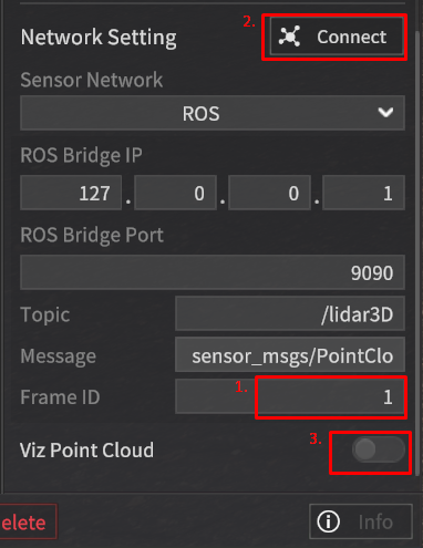
1) Frame ID 를 “1“ 로 수정
2) Network Setting 창 상단에 위치한 를 클릭하여 ROS 연결
3) Viz Point Cloud 토글 스위치를 on 하여 시뮬레이터에서 Point Cloud Data 비주얼라이제이션
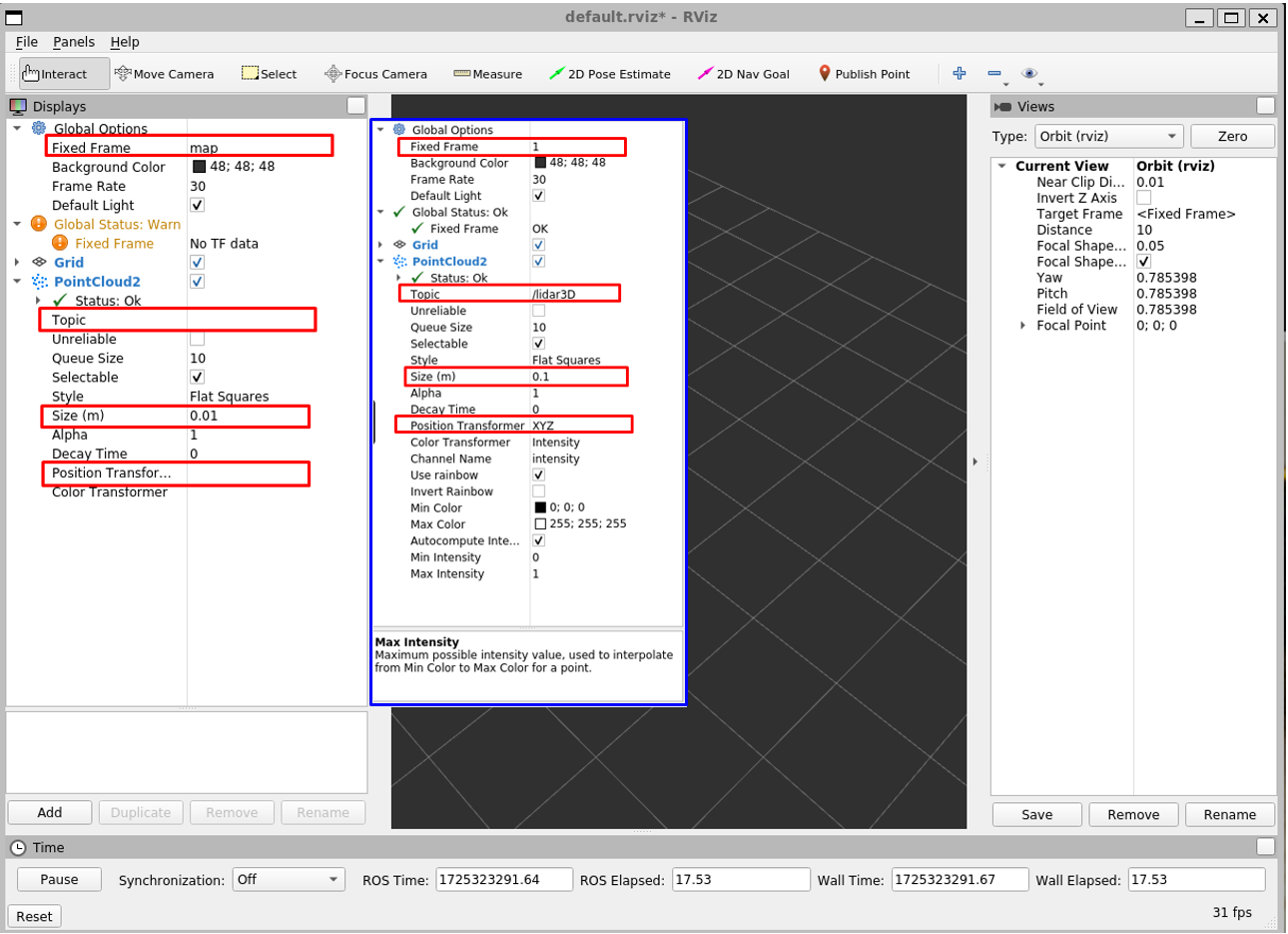
시뮬레이터 내 세팅 완료 후, Rviz 세팅
파란색으로 표시된 부분의 값들을 참고하여 Rviz 에 각 항목 입력
4. Custom LiDAR 의 Visualization
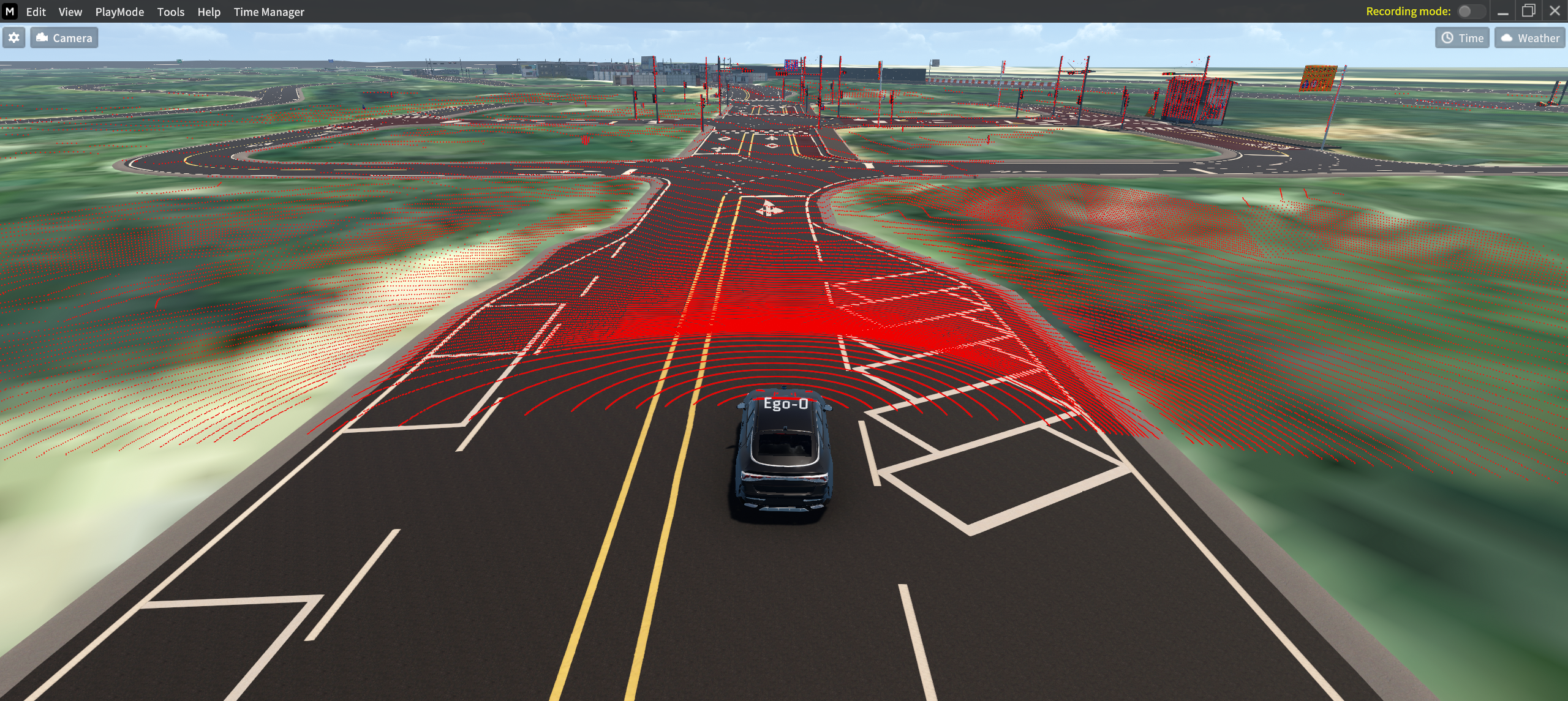
1] 시뮬레이터
시뮬레이터에서 보이는 Custom LiDAR 의 Visualization 은 아래 이미지와 같다.
2] Rviz
Rviz 로 Custom LiDAR 의 Visualization 을 한 모습은 아래 이미지와 같다.
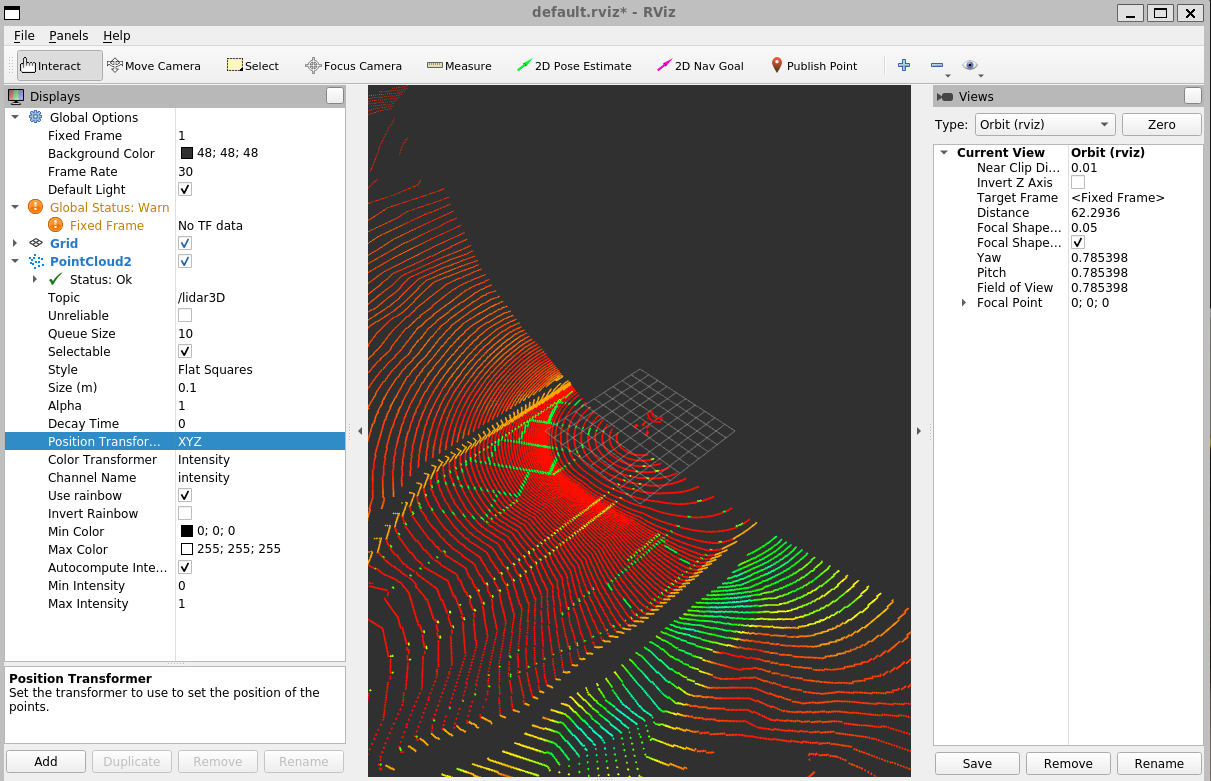
다른 Sensor 와 마찬가지로 ROS bridge 를 연결하여 해당 데이터를 수신 받을 수 있다.